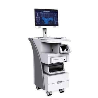
What are the maintenance methods for LCD screens:
1. Observation method:
Observation method is to check the obvious problems of the display by seeing, hearing, touching, nose and so on. Observe not only carefully, but also comprehensively. The usual observations include: the surrounding environment (including power supply environment, other high-power appliances, magnetic field conditions, temperature/humidity environment, environmental cleanliness, etc.) and whether there are abnormal phenomena such as deformation, discoloration, and peculiar smell inside the display, such as whether the insurance tube If it turns black, whether there is any abnormality in the filter capacitor, and whether there are obvious virtual solder joints. By observing and searching for significantly damaged components, you can roughly determine the size and scope of the problem, and even find the problem immediately.
2. Visual inspection method:
Intuitive inspection method means that when the display is working abnormally, most of the problem phenomena can be observed from the display screen and other monitors (such as flower screen, color problems, etc.). According to the observed problem phenomenon, combined with the cause and process of the problem provided by the user during the overhaul, the parts where the problem may occur are preliminarily judged after analysis. Since the circuit structure of the display is relatively complicated, the same problem phenomenon may occur in different parts of the problem, that is, a problem phenomenon may be caused by multiple reasons. This requires careful observation, inspection and analysis, and then go to the rough, remove the false and save the truth, and finally find out the real problem part until the problem is eliminated.
LCD
3. Static resistance measurement method:
The static resistance measurement method mainly measures whether there are significant short circuits and short-circuit components. The short-circuit components must be eliminated before power-on and overhaul, otherwise the problem will be enlarged and the maintenance difficulty and cost will be increased.
4. Current measurement method:
Measuring current is one of the basic ways of repairing circuits. It is a way to measure the load current and working current of transistors and IC chips. This method is used to detect whether the integrated circuits, transistors and their power loads are normal. If the working state of the transistor or IC chip is normal, then the measured load current should be normal. If the measured current changes greatly compared with the normal value, then the circuit may have a problem, and you can focus on it. .
5. Voltage measurement method:
Another method often used in repairing display circuits is the voltage measurement method, which mainly measures the working voltage of the circuit and components to determine the problem location and components. Such as measuring whether the plus 300V DC voltage in the power supply circuit is normal, whether the starting voltage is normal, whether the protection circuit is active, whether the output voltage is normal, etc.
6. Method of measuring resistance:
The resistance measurement method is also one of the basic ways to repair the display circuit. It is mainly divided into two types of measurement: one is to measure the resistance of the display circuit and components to ground; the other is to measure the resistance of the components themselves. By measuring the resistance to ground at the output of the circuit, it can be judged whether the load of the circuit is normal. For example, when measuring the resistance to ground at the output of the power supply, if the load resistance changes significantly, the resistance to ground at the output of the power supply will inevitably change. This makes it easy to determine the problem. When measuring the resistance of each pin of a transistor or IC chip to the ground, you need to measure its forward and reverse resistance. Normally, the resistance measured when the negative meter pen is grounded is the positive resistance, and when the positive meter pen is grounded. The resistance value of is reverse resistance. This can be compared with the resistance value under normal conditions based on the change in the measured resistance value to determine the problem.
7. Short circuit method:
The short-circuit method is mainly used to simulate the saturation and cut-off of the triode. The specific measurement method is as follows: Use tweezers to short-circuit the BE junction of the triode, and the triode must be cut off due to the short-circuit of the BE junction. In some circuits, the CE junction of the triode can also be short-circuited to simulate the saturation of the triode. This operation requires familiarity with the circuit. In the switching power supply circuit, try not to use this method. For example, the CE junction of the power switch tube must not be short-circuited.
8. Adjust the input voltage method:
The method of adjusting the input voltage is a method adopted for safety inspection. For example, externally connect the line output circuit with a stable voltage that meets the requirements of the line output circuit to determine the problem. Of course, the result is that the grating is reduced under normal conditions. If this result can be obtained, it indicates that the line output circuit is basically normal. For another example, connect the 7th pin of the UC3842 in the switching power supply circuit to an external plus 17V voltage. If the UC3842 itself and the peripheral circuit are normal, its 6th pin should output pulse voltage (the switch tube must be removed here, otherwise , No voltage regulation adjustment will destroy the switch tube and UC3842).
9. Replacement method:
The replacement method is to replace the problematic components with good components to find out the problematic components (good components should be of the same model as the problematic components). Firstly, check whether there is any problem with the line connected to the component that may have a problem, then check whether the power supply is normal, then replace the component that may have the problem, and finally replace other related components. Complicated sequence.
10. Parameter measurement method:
Parameter measurement method refers to the use of pointer multimeter or digital multimeter to measure component voltage, resistance and current parameter values, and then compare and analyze with the standard parameter values in the maintenance manual, so as to find the problem component. For maintenance in this way, you need to prepare a maintenance manual for the monitor. Use the voltage method and the resistance method to measure the circuit state voltage and the resistance in the circuit. The readings of multimeters of different models are different because of the different internal resistances of the meter heads. In order to avoid comparison and analysis errors caused by measurement reading errors, it is best to use a multimeter of the same model for measurement.
11, cleaning repair welding method:
The cleaning and repair welding method first clean the circuit board of the display with absolute alcohol to remove dust, stains, mildew, rust and other substances in the circuit board, and then repair the areas that may be corroded or poor contact in the display. . Because the monitor is exposed to humidity, dust, high temperature and other environments, it will cause the internal circuit to short-circuit or form a conductor with a certain resistance value, thereby destroying the normal operation of the circuit. (Note: After cleaning the circuit boards and other components, dry the circuit boards with hot air before they can be installed for testing.
12. Oscilloscope observation method:
In the circuit of the display, some important waveforms have no test points (TP) on the printed circuit board. The shape, width and amplitude of the wave have strict requirements and are marked on the pattern. The problematic part can be found quickly and accurately by inspecting and observing the waveform.
13. Comparison method and replacement method:
Comparison method and replacement method refer to the use of a normal monitor of the same model and a problematic monitor to compare the measurement of the same part. Two monitors of the same model can be compared by measuring the voltage of the same part, the resistance of the circuit or observing the signal waveform with an oscilloscope under the same working condition. You can also use components with good performance (including mechanical parts and printed circuits). Board components, etc.) Perform replacement verification for components that may be damaged. It can accurately verify the quality of the components by adopting the method of measurement and comparison of the same part and replacement verification.
14. Dummy load method:
The so-called false load is a protective detection method to avoid other problems caused by the increase in output voltage when the switching power supply is under light load after the line load is disconnected, so as to determine the scope of the problem. The method of the false load method Many, there are two main ones. One is to disconnect the main voltage and the line circuit, and connect a 60W/220V bulb to both ends of the plus B1 (line output voltage) filter capacitor. The advantage is that it is easy to obtain materials, but the disadvantage is that the cold resistance of the bulb is small, which makes the switching power supply. It is not easy to start, which brings judgment errors to the maintenance, but it is still usable under normal circumstances.
Another approach is to connect a 50W/300Ω resistor, which can more accurately simulate the line output stage load. However, whether the output voltage is normal or not cannot be seen directly, and it is difficult to obtain materials. When using the dummy load method, pay attention to the fact that the line output stage does not work. The plus B2 (line output power supply) without feedback signal may increase the output voltage of the power supply to more than 200V, so it is best to stop the plus B2 regulator tube from working, and at the same time Also make the line output stage stop working. Tip: (When using a dummy load for maintenance, the control gate of the FET can not be left floating, you can disconnect the source power supply or simply remove it, and then install it after repair, or you can use a small piece of wire to connect the control electrode to the drain The poles are connected).
15. Percussion, vibration method:
Percussion and vibration methods mean that the monitor runs well and is susceptible to vibration. It may be caused by the increase in contact resistance of the components due to virtual welding, poor contact or metal oxidation. When this problem occurs in the monitor, it is effective to use the percussion vibration method to repair it. Tap the circuit board lightly with the tip of your finger or an insulating stick, or twist the circuit board lightly, or press lightly in the center of the circuit board to make the problem manifest as soon as possible. At the same time, pay attention to the changes in the phenomenon of the problem. When the problem is manifested, use the voltage detection method to detect it. Tip: (Sometimes, when the circuit board is vibrated in the dark (turn off the light), if a spark is found, it is a problem). In addition, there are methods such as temperature rise method and contrast method. It is also essential to ask the user about the operation process of the display, the time and phenomenon of the problem.